¶ Network Setup Tips
The BlackPearl management port is separated from the data ports. The management port and data ports have their own default routes. This does not prevent a user from having the management and data ports utilizing the same network, if desired.
The basic steps for configuring the management and data ports for access to the network are simple and straight-forward. However, each network environment is unique and may require some additional troubleshooting in order to properly connect to the BlackPearl system and utilize the Ethernet interfaces correctly.
The first step is to configure the management and data ports using the BlackPearl user interface or the command line interface. Do not attempt to access the system directly and use the root console to modify interfaces. The web and command line interfaces are tightly integrated with the base operating system and configure additional system features based on network changes.
The following configurations are supported for the data path:
Recommended:
For the 10 GigE optical:
- Single 10 GigE logical connection using one of the 10 GigE physical ports
—OR—
- Single 20 GigE logical connection using two 10 GigE physical ports (link aggregation)
For the 40 GigE optical:
- Single 40 GigE logical connection using one of the 40 GigE physical ports
—OR—
- Single 80 GigE logical connection using two 40 GigE physical ports (link aggregation)
For the 10GBase-T:
- Single 20 gigabit logical connection using two 10GBase-T physical ports (link aggregation)
—OR—
- Single 30 gigabit logical connection using three 10GBase-T physical ports (the two ports on the card and the one spare onboard port) (link aggregation)
For the 25 GigE optical card: (Gen2 only):
- Single 25 GigE logical connection using one of the 25 GigE physical ports
—OR—
- Single 50 GigE logical connection using two 25 GigE physical ports (link aggregation)
For the 100 GigE optical:
- Single 100 GigE logical connection using one of the 100 GigE physical ports
—OR—
- Single 200 GigE logical connection using two 100 GigE physical ports (link aggregation)
Not Recommended:
- Single gigabit logical connection utilizing one of the 10GBase-T physical ports and a Category 5e Ethernet cable
Assign the appropriate IP address to the management and data ports either statically or using DHCP. If you are setting the MTU to something other than 1500, ensure that your switch configuration, as well as all the hosts on the network, support larger MTU settings. The BlackPearl system can support jumbo frames (MTU=9000), but all switches and hosts on the network must be configured to support jumbo frames if this is selected, or performance might be degraded.
¶ Notes on specific networking card options
From Jan 2023 onwards, Spectra Logic has moved away from specific networking cards to using specific SFP+/SFP28/QSFP/QSFP28 options to rate limit networking cards. This reduces the need for lift and shift upgrades. In most cases simply replacing the SFP+/QSFP will allow for networking upgrades to take place without having to schedule a full maintenance window
A typical example of this, is that when 10Gbit network connection is required, Spectra Logic will ship a 25Gbit network card with both 25Gbit SFP28's and 10Gbit SFP+ modules. When the networking infrastructure is upgraded to support 25Gbit, the 10Gbit SFP+ modules can be replaced for the 25Gbit SFP28's with little to no downtime.
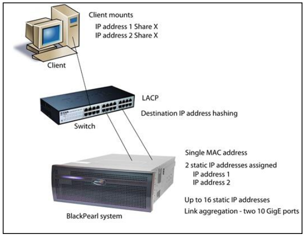
Switches use different methods of routing traffic from hosts to NAS servers. There are also many different network configurations to move data from hosts to NAS servers. For example, some Cisco switches route traffic based on the MAC address and the IP address. The BlackPearl system presents only one MAC address and one IP address when the data ports are aggregated via DHCP; if static link aggregation is chosen, the BlackPearl system presents only one MAC address, but can have up to 16 IP addresses aliased to the MAC address. It is up to the switch to rotate data transfers among the physical ports on the BlackPearl system in order to achieve the highest throughput possible.
Additionally, if link aggregation is configured for the BlackPearl system, then switches must also be able to support link aggregation to aggregate or “trunk” the data ports together to provide higher bandwidth into the system. Switches must support link aggregation using LACP (Link Aggregation Control Protocol), and the switches must hash the destination IP addresses. Manually configure LACP on the switch ports. LACP does not get enabled automatically.
For example, if only a single host is connected to the BlackPearl system through a link aggregated connection, the measured performance is lower than the potential maximum transfer rate because only one physical port of the two port link aggregation is being utilized by the switch. If a single share is mounted two times using different IP addresses and transfers are started to that share from two separate hosts, the resulting throughput would be approximately twice that of a single host connection. You may need to configure more than two IP addresses on the BlackPearl system to force the switch hashing algorithm to utilize all physical ports to maximize performance.
Once configured correctly and attached to the network, the status in the user interface indicates the speed of the connection and whether the port is active. The link lights on the network ports should be on and active at both the BlackPearl system and the network switch.
From your network, use the “ping” command to test the assigned IP address for the BlackPearl management port or data port. If this is not successful, use the following troubleshooting tips to ascertain if the problem is a network setup issue.
Port Link LED Does Not Light
- Check the port configuration on the network switch. The BlackPearl system only supports auto-negotiation. Make sure the switch is configured to match speeds on both ends of the connection.
- Check the cables that connect the port to the other device. Make sure that they are connected. Verify that you are using the correct cable type and connectors. This is especially critical for 10 GigE and 40 GigE connections utilizing SFPs.
- Verify that the switch ports are not administratively disabled. Consult the switch User Guide for more information.
Port Link LED is Lit, But I Cannot Ping the BlackPearl System
- Check the LACP settings on the switch. If you are using link aggregation on the BlackPearl system, the switch MUST be configured to use LACP on those ports. If you are not using link aggregation, the switch must be configured NOT to use LACP on those ports.
- Check the VLAN (Virtual Local Area Network) settings on the switch. Ensure that the ports are assigned to the correct VLAN
¶ Tools
Ping
The ping command is a simple tool, based on a request-response mechanism, to verify connectivity to a remote network node. The ping command is based on ICMP (Internet Control Message Protocol). The request is an ICMP Echo request packet and the reply is an ICMP Echo Reply. Like a regular IP packet, an ICMP packet is forwarded based on the intermediate routers' routing table, until it reaches the destination. After it reaches the destination, the ICMP Echo Reply packet is generated and returned to the originating node. For example, to verify the connectivity from the switch to the IP address 192.168.2.10, run the command shown below from the switch command line or client:
ping 192.168.2.10
All ICMP Echo requests should receive replies including information about the round trip time it took to receive the response. A response of 0 msec means that the time was less than 1 ms. If the request times out, then check the settings on the switch to which the BlackPearl system is connected.
Traceroute
You can use the traceroute command, if it is available, or something similar, to not only verify connectivity to a remote network node, but to track the responses from intermediate nodes as well. The traceroute command sends a UDP packet to a port that is likely to not be used on a remote node with a TTL of 1. After the packet reaches the intermediate router, the TTL is decremented, and the ICMP time-exceeded message is sent back to the originating node, which increments the TTL to 2, and the process repeats. After the UDP packet reaches a destination host, an ICMP port-unreachable message is sent back to the sender. This action provides the sender with information about all intermediate routers on the way to the destination.
For example, for a BlackPearl system at IP address 192.168.2.10, the output of the command shown below,
traceroute 192.168.2.10
shows a numbered list indicating the number of hops encountered when tracing the packet from the switch to the BlackPearl system